Reactive Load Box Schematic

Diy Box Mod Dual 18650 Parallel Dual Mosfet Schematic Ide Produk

New Wiring Diagram Three Phase Generator Diagram Diagramsample Diagramtemplate Check More At Https Morningculture C Diagram Auto Transformer Diagram Chart

Music Led Light Box Modified Circuit Diagram Circuit Diagram Led Light Box Electrical Engineering Books

15 Stunning Crossover Wiring Diagram Car Audio Design Ideas Https Bacamajalah Com 15 Stunning Crossover Wi Car Audio Systems Diy Car Audio Custom Car Audio
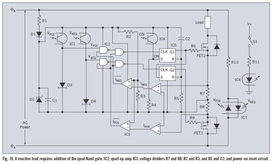
Image Result For Power Supply For Tattoo Machine Diagram Tattoo Kits Tattoo Machine Diagram

Few Lm317 Voltage Regulator Circuits That Has A Lot Of Applications Voltage Regulator Electronic Circuit Projects Regulators

Schematic for 3a load box.
Reactive load box schematic. Designing a reactive speaker load emulator. Starting from the randall aiken paper on a reactive load box i combined that with 3 attenuation level 6 12 and 18db selectively sending more and more current through the reactive side instead of the speaker plus an l pad for fine volume control. A speaker presents a varying impedance load to the amp. This circuit will apply a resistive based load to safely discharge a tube amp v.
The reactive load is dedicated to being the absolute best load box possible with zero compromises and therefore does not include speaker emulation. If you want to make a fully adjustable load box add a 1mω log taper pot or 10 turn 100kω pot between u1a and u1b. You can use the reactive load with your speaker sim or impulse response of choice and benefit from the natural response dynamics and touch sensitivity of your amp. The stated impedance is usually measured at 400hz and can vary widely over the frequency range.
Aiken dummyload diy project pdf aiken dummyload tech paper. The opamp an lt1635 also contains a buffered 200mv reference u1a which is amplified to obtain 3v. I trimmed the output current to 3a by adding 2mω across r6. Links to power attenuator schematics and dummy load schematics.

Electricity Power Saver For Home Application Power Saver Energy Saving Devices Electricity

P43 Grid Synchronisation With Harmonics And Reactive Power Compensation Capability Of A Permanent Magnet Synchronous Generator Based2009 Permanent Magnet Power Generation

8 Schemes To Supply Mv Switchboard Eep Electrical Circuit Diagram Single Line Diagram Line Diagram

Engl Amp Heads Electric Guitar And Amp Cool Guitar Guitar Amp

Equivalent Circuit Diagram Of A Network With Different Loading A Equivalent Circuit B Phasor Diagram Power Circuit Diagram Some Words

This Is A Voltage Controller Circuit With Ampere Using Irf540n We Can Use 0 Volt To 100 In 2020 Electrical Circuit Diagram Electronic Circuit Projects Simple Circuit

Because The Egs 02 Control System Realizes The Closed Loop Control Of The Running Process It Ensures That The Control Control Control System Diesel Generators

Washing Machine Motor Controller Full Project Available Electronics Basics Washing Machine Motor Iot

140w Power Amplifier Circuit Tip3055 Tip2955 Circuit Diagram Power Amplifiers Circuit

Gt Gt Eew 39 S Vision Electrical Engineering World Is The Worldwide Com Electrical Engineering Books Electrical Circuit Diagram Electrical Engineering

Simple And Useful Led Circuits Met Afbeeldingen

Kenwood Ddx719 Wiring Diagram Diagram Kenwood Wire

Emergency Generator Set Construction Installation Maintenance Wiring Emergency Generator Electronic Engineering Generator Installation

Wiring Two Outlets In One Box Using Pigtail Splices Outlet Wiring Electrical Outlets Light Switch Wiring

Subwoofer Speaker Amp Wiring Diagrams Kicker Car Audio Subwoofer Speaker Car Audio Installation
Pin On Ieee Fyp

Darlington Motor Speed Control Electronic Circuit Projects Electronics Engineering Projects Electronics Mini Projects

Pin On Ieee Fyp
3

Sonos Connect Mod Modification Add 12 Volt Remote Trigger Amp Turn On Youtube Sonos Connect Sonos Light Accessories

Image Result For Lm317t Laser Driver High Speed Photography Electrical Circuit Diagram Diy Laser Engraver

Clean Wiring Dash Google Search Diy Car Electronics Diy

How To Protect Capacitor Banks Eep Capacitors Electrical System Electricity

Solusi Battery Cara Mudah Membuat Kiprok Fullwave Regulator Pengisian Aki

Make Music Reactive Led Lights Using Mosfet Sensitive Sound Detector Youtube Electronic Circuit Projects Electronics Projects Diy Led Lights

4 Example Calculations Of Compensation For Reactive Power

Star Delta Starter Y D Starter Power Control Wiring Diagram Delta Connection Electrical Circuit Diagram Electrical Projects

Pin By Muzammil Iqbal On Genset Installation Generator Installation Transfer Tanks Plates On Wall

How Electricans Test Continuity Of Protective Conductors Eep Conductors Continuity Electrician


Gear Review Genzler Acoustic Array Mini Acoustic Guitar Amp Arrays

Youtube Led Strip Led Diy Led

Image Result For Power Supply For Tattoo Machine Diagram Tattoo Kits Tattoo Machine Diagram

Pin On Modul

Suburban Water Heater Wiring Diagram Denso Alternator Alternator Diagram

What Is An Electric Circuit Types Of Circuits Network Parts Of Circuit Electric Circuit Electric Circuit Analysis Circuit

Stm32f103rct6 Mini Dev Board R3 64p Electrodragon Development Board Usb Stick Mini

Boss Waza Tube Amp Expander Amps Preamps Chicago Music Exchange Boss Effects Logic Design Tube

Marshall Sv20h Studio Vintage 20 5 Watt Tube Head Guitar Amp Guitar 90s Era

Esp32 Handheld Game Console Programmirovanie


This Is A Voltage Controller Circuit With Ampere Using Irf540n We Can Use 0 Volt To 100 In 2020 Electrical Circuit Diagram Electronic Circuit Projects Simple Circuit

